Bridge Health Monitoring System Using ESP32 and Flex Sensor
📌 1. Detailed Introduction
Bridges are critical infrastructure components that connect cities, towns, and transportation networks. They continuously experience dynamic loads from vehicles, environmental forces such as wind and temperature changes, and long-term material fatigue. Over time, these stresses can cause structural deformation, bending, cracks, or even collapse if not monitored properly.
Bridge Health Monitoring (BHM) systems are developed to continuously observe the structural condition of bridges and detect early signs of damage. Traditional systems use advanced sensors like strain gauges, accelerometers, and crack detectors. However, these systems can be expensive and complex.
This project presents a simplified and cost-effective prototype of a Bridge Health Monitoring System using an ESP32 microcontroller and a flex sensor. The system is designed to detect bending in a bridge model. When the bridge bends beyond a safe limit, the system identifies the deformation and indicates a warning message “Bend Detected.” If the structure remains stable, it displays “No Bend.”
The purpose of this project is to demonstrate how sensor-based monitoring systems can detect structural deformation in real time and help prevent structural failure.
🌉 2. Concept of Bridge Health Monitoring
Bridge Health Monitoring refers to the continuous observation and evaluation of a bridge’s structural integrity using sensors.
Why Monitoring is Important:
-
Detect early structural damage
-
Prevent catastrophic failures
-
Reduce maintenance costs
-
Ensure public safety
-
Enable predictive maintenance
In real-world applications, engineers use:
-
Strain Gauges (measure strain)
-
Accelerometers (measure vibration)
-
Crack Sensors (detect crack growth)
-
Load Cells (measure applied load)
In this project, a flex sensor is used to simulate structural bending detection.
🔎 3. Component Introduction
🟢 3.1 ESP32 Microcontroller
The ESP32 is a powerful microcontroller used for IoT and embedded systems.
Key Features:
-
12-bit Analog-to-Digital Converter (ADC)
-
Multiple GPIO pins
-
Built-in WiFi and Bluetooth
-
Low power consumption
-
High processing speed
Role in Project:
-
Reads analog voltage from flex sensor
-
Compares value with predefined threshold
-
Determines bridge condition
-
Displays bend status
The ESP32 acts as the brain of the system.
🟢 3.2 Flex Sensor (Main Component)
What is a Flex Sensor?
A flex sensor is a variable resistor whose resistance changes when bent.
It is a thin, flexible strip made of conductive material embedded in a flexible substrate.
Internal Working of Flex Sensor


Inside the flex sensor:
-
Conductive ink or carbon particles are embedded.
-
When straight → particles are closer → lower resistance.
-
When bent → particles move apart → higher resistance.
Resistance Behavior:
-
Straight position → approximately 10kΩ
-
Bent position → 20kΩ to 30kΩ or more
This change in resistance is the key working principle.
🟢 3.3 Resistor (10kΩ)
A fixed resistor is used to create a Voltage Divider Circuit.
Why needed?
The ESP32 cannot measure resistance directly.
It can only measure voltage.
So resistance change must be converted into voltage change.
🟢 3.4 Breadboard & Connecting Wires
Used to assemble and connect all components without soldering.
🔌 4. Connection Diagram Explanation (Without Code)
Voltage Divider Circuit
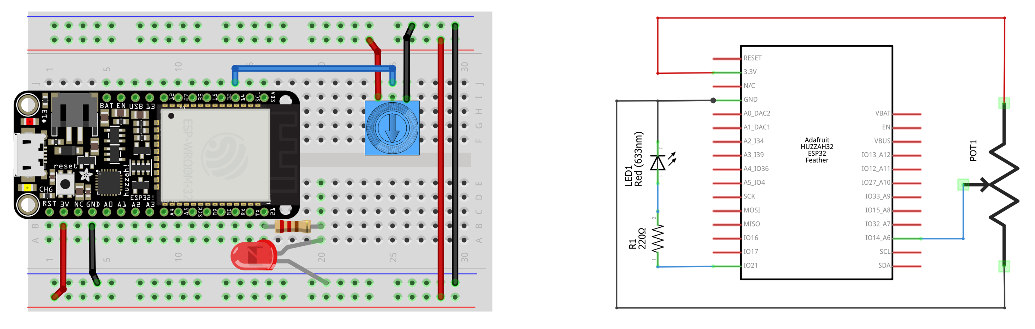
Connections:
-
One end of Flex Sensor → 3.3V (ESP32)
-
Other end of Flex Sensor → Analog Pin (GPIO 34)
-
10kΩ Resistor connected between GPIO 34 and GND
This forms a voltage divider.
Why Voltage Divider Works?
Voltage Divider Formula:
Vout = Vin × (R2 / (R1 + R2))
Where:
-
R1 = Flex sensor resistance
-
R2 = 10kΩ resistor
-
Vout = Voltage read by ESP32
When flex sensor bends:
-
R1 increases
-
Output voltage changes
-
ESP32 detects voltage variation
⚙️ 5. Detailed Working Logic (Step-by-Step)
Step 1: Normal Condition
-
Bridge is straight.
-
Flex sensor is straight.
-
Resistance is low.
-
Voltage at analog pin is within normal range.
-
System displays “No Bend.”
Step 2: Load Applied on Bridge
-
Load causes slight bending.
-
Flex sensor bends with structure.
-
Resistance increases.
Step 3: Voltage Change
-
Because resistance increased,
-
Voltage at analog pin changes.
-
ESP32 reads higher analog value.
Step 4: Threshold Comparison
The ESP32 compares:
-
Current analog value
With -
Predefined safe threshold value
If value > threshold:
→ Bridge bending beyond safe limit
→ “Bend Detected”
If value ≤ threshold:
→ Safe condition
→ “No Bend”
📊 6. Logical Flow of System
-
Start system
-
Read analog voltage
-
Convert voltage to digital value (ADC)
-
Compare with threshold
-
Display bridge condition
-
Repeat continuously
🎯 7. Objectives of the Project
-
To design a simple bridge deformation detection system
-
To understand sensor-based structural monitoring
-
To implement low-cost monitoring using ESP32
-
To simulate real-world structural health monitoring
⚠️ 8. Limitations of the Project
-
Only detects bending, not cracks or vibration
-
Suitable for model demonstration only
-
Not industrial-grade accuracy
✅ 9. Conclusion
The Bridge Health Monitoring System using ESP32 and flex sensor is a simple prototype that demonstrates how structural bending can be detected using resistance-based sensors. The flex sensor detects deformation by changing its resistance, which is converted into voltage through a voltage divider circuit. The ESP32 processes this signal and determines whether the bridge is in safe condition or under stress.
Although this system is a basic prototype, it clearly illustrates the fundamental principles of real-time structural health monitoring and can be expanded into advanced systems using additional sensors and wireless communication technologies.